I’m building a rover that can navigate my neighborhood autonomously. GPS waypoints, curb climbing, the whole deal. The goal is to deliver homebrew to my neighbors without me having to walk it over myself. I make beer, they get beer, everybody wins. Except now I have to build a robot.
Here’s the thing about building robots: you don’t just learn one skill. You learn twelve. I started this project knowing how to write software. Now I’m doing CAD modeling, Ackerman steering geometry, aluminum fabrication, 3D printing in multiple materials, ArduPilot configuration, and spending way too much time thinking about gear ratios. Each problem solved reveals three more problems I didn’t know existed.
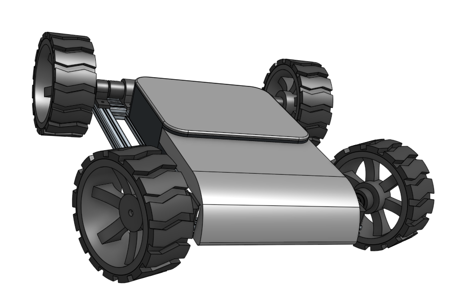 CAD render of the current design
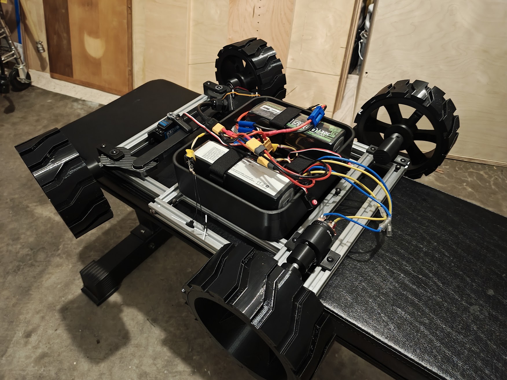 Current state of the build
Current Status
The drivetrain is the current focus. The gearbox is working and integrated — it took a dual cardan universal joint to solve a height alignment issue between the gearbox output and the wheels, and a full redesign to fix a motor collision when mirroring to the other side. Right now I’m printing parts and assembling, waiting to find the next problem.
Build Progress
Frame and Body
The frame is 2020 T-slot aluminum extrusion, 24” x 18”. It’s basically adult LEGO. I can move things around, drill new holes, and adjust the layout without starting over. The joints use M6 tapped holes. I learned to tap threads into aluminum, which is more satisfying than it has any right to be.
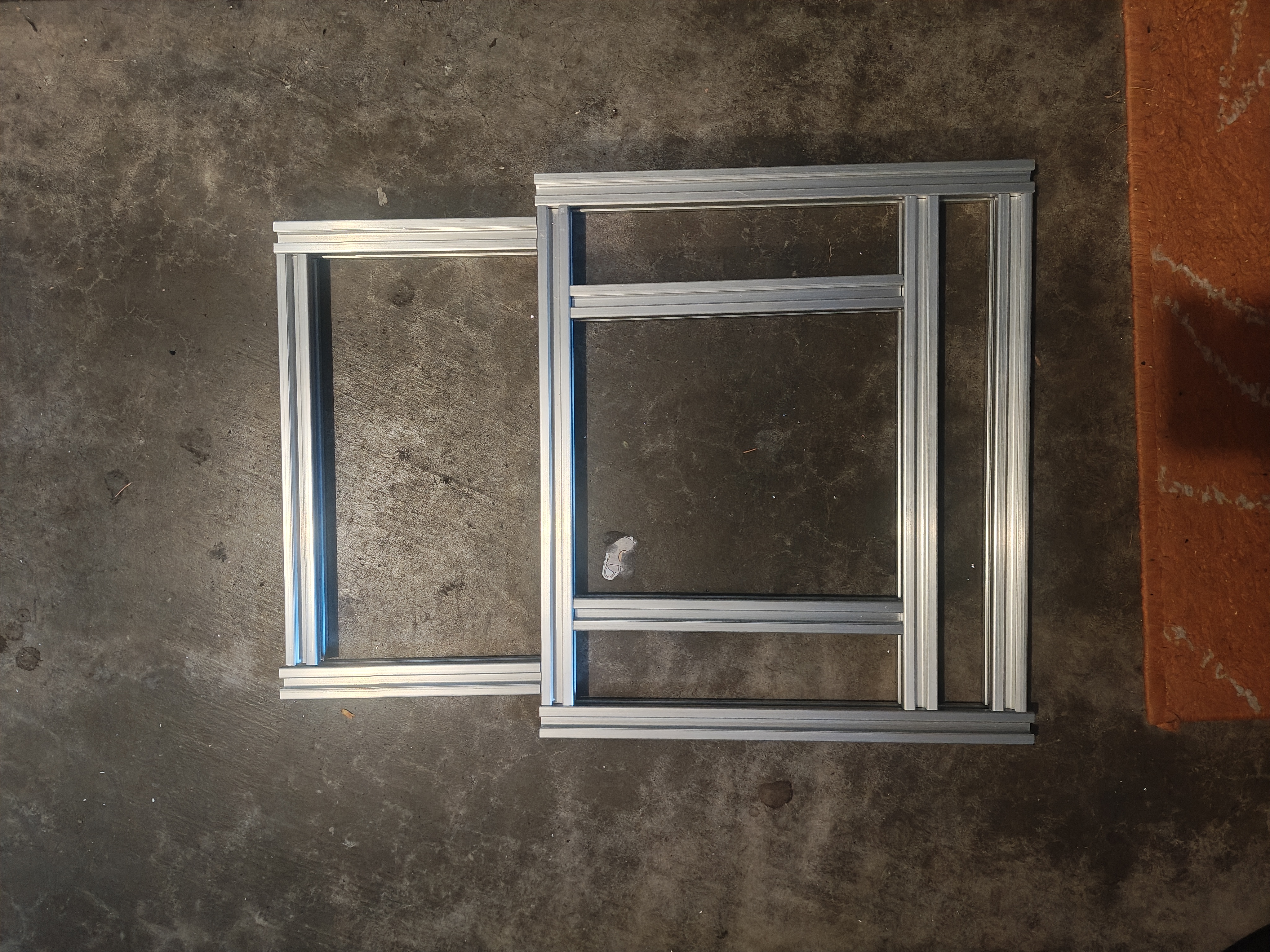 Cut 2020 extrusion pieces before assembly
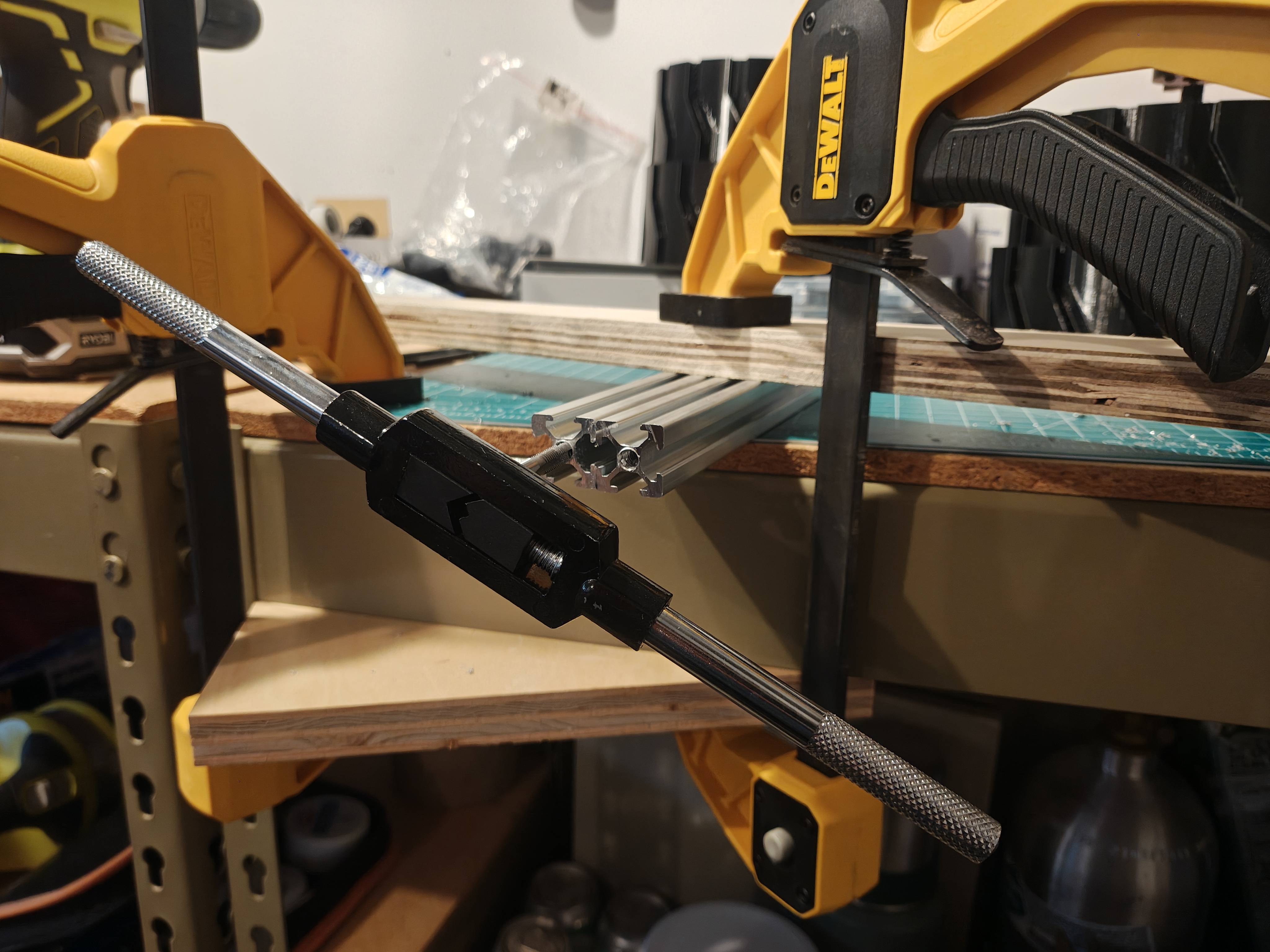 Tapping M6 threads by hand
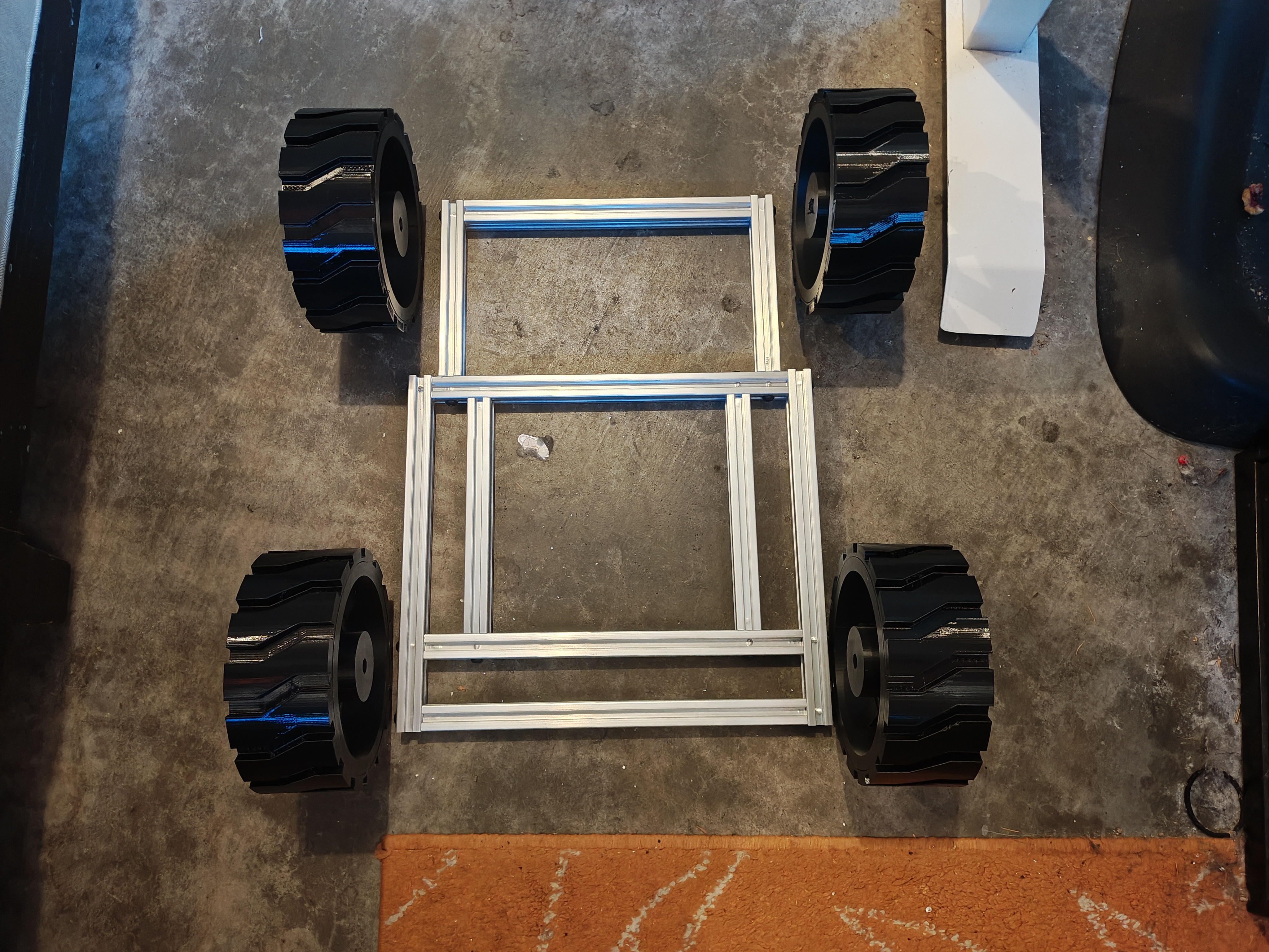 First mockup with wheels placed for sizing
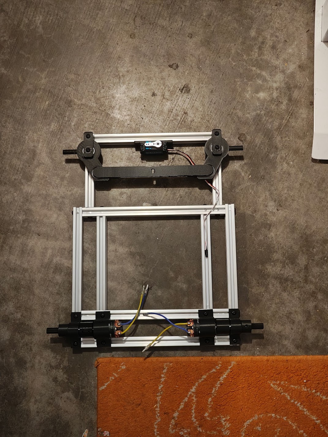
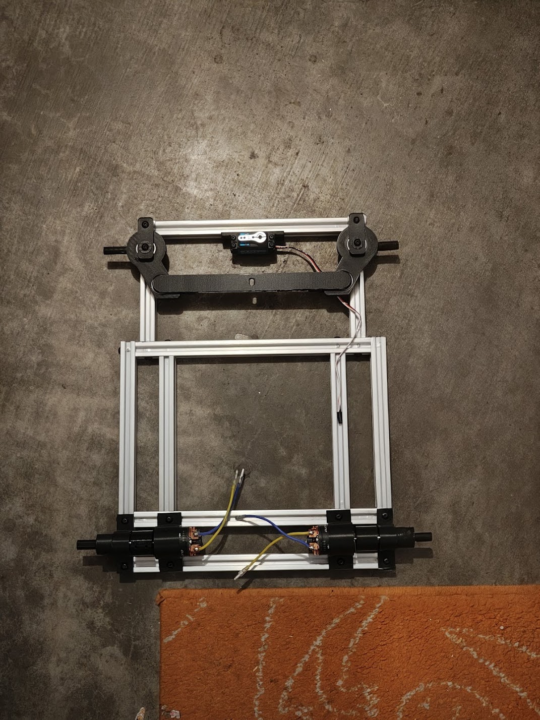 Frame with steering and motor mounts installed
Drivetrain
 Drivetrain — gearboxes, CV joints, and wheels
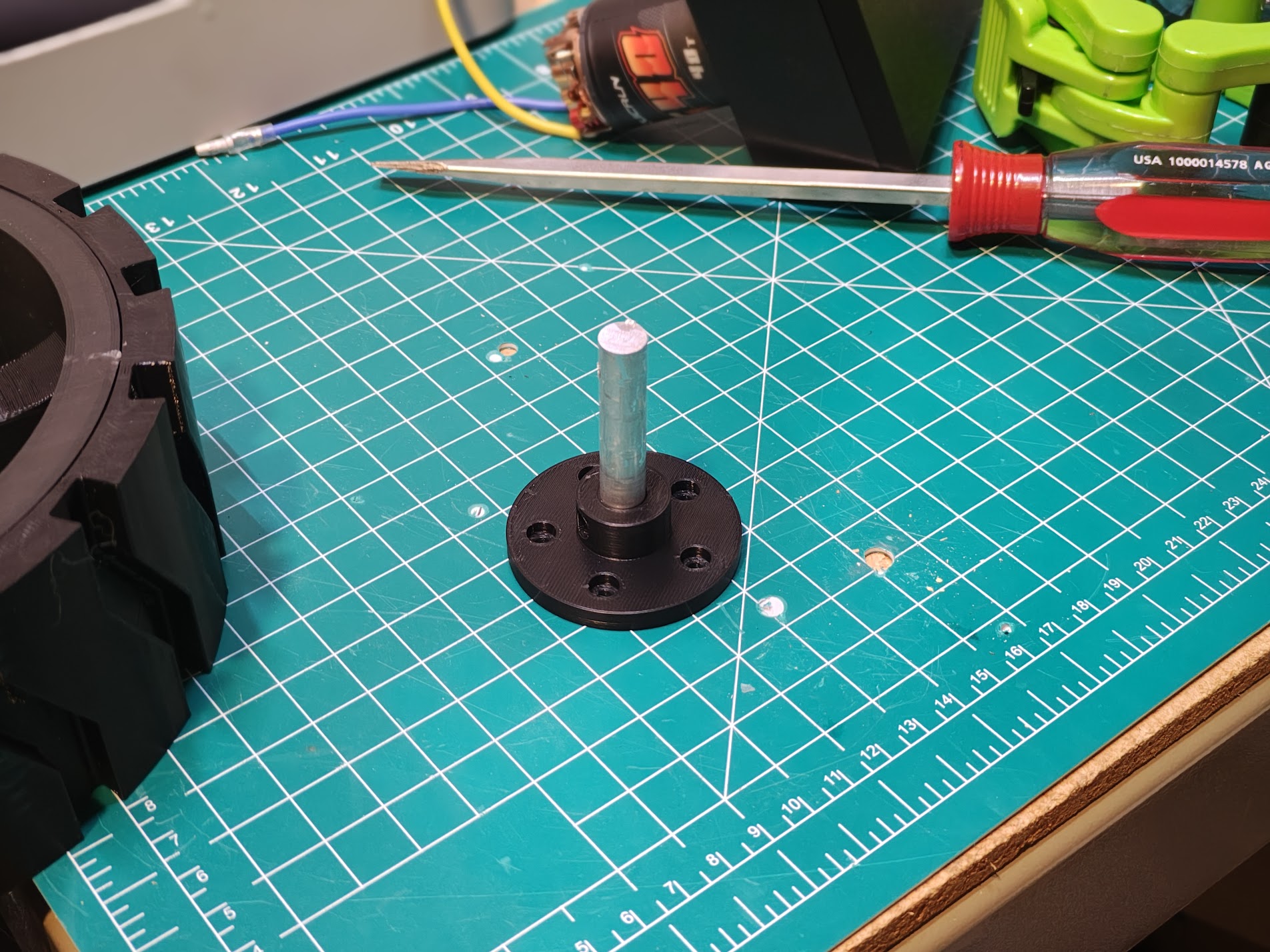
Two motors, two ESCs, one dream. The HOBBYWING QUICRUN 1080 G2 ESCs drive 540 40T brushed motors. Brushless would be more efficient, but at 3 mph efficiency doesn’t matter. Brushed motors give smooth low-speed control without sensored feedback or fancy ESC tuning, and they’re cheaper. Getting power from the motor shafts to the wheels required flexible couplers. Rigid connections would bind up with any misalignment, and there’s always misalignment. The bearings are 6000RS with a 10mm bore, and I spent way too long getting the shaft diameter right. 9.98mm fits a 10mm bore smoothly. 10.02mm does not.
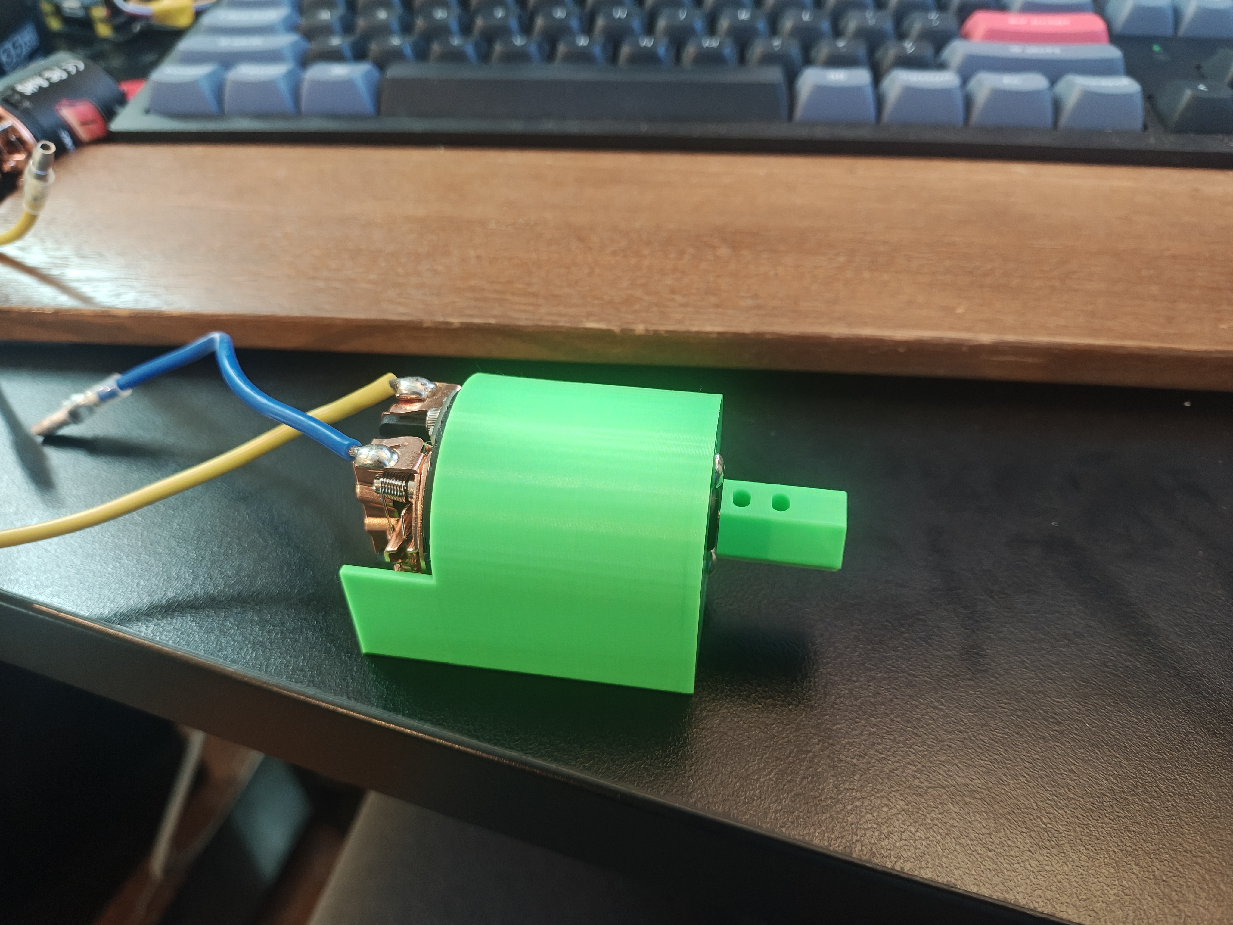 Early motor mount prototype with flexible coupler
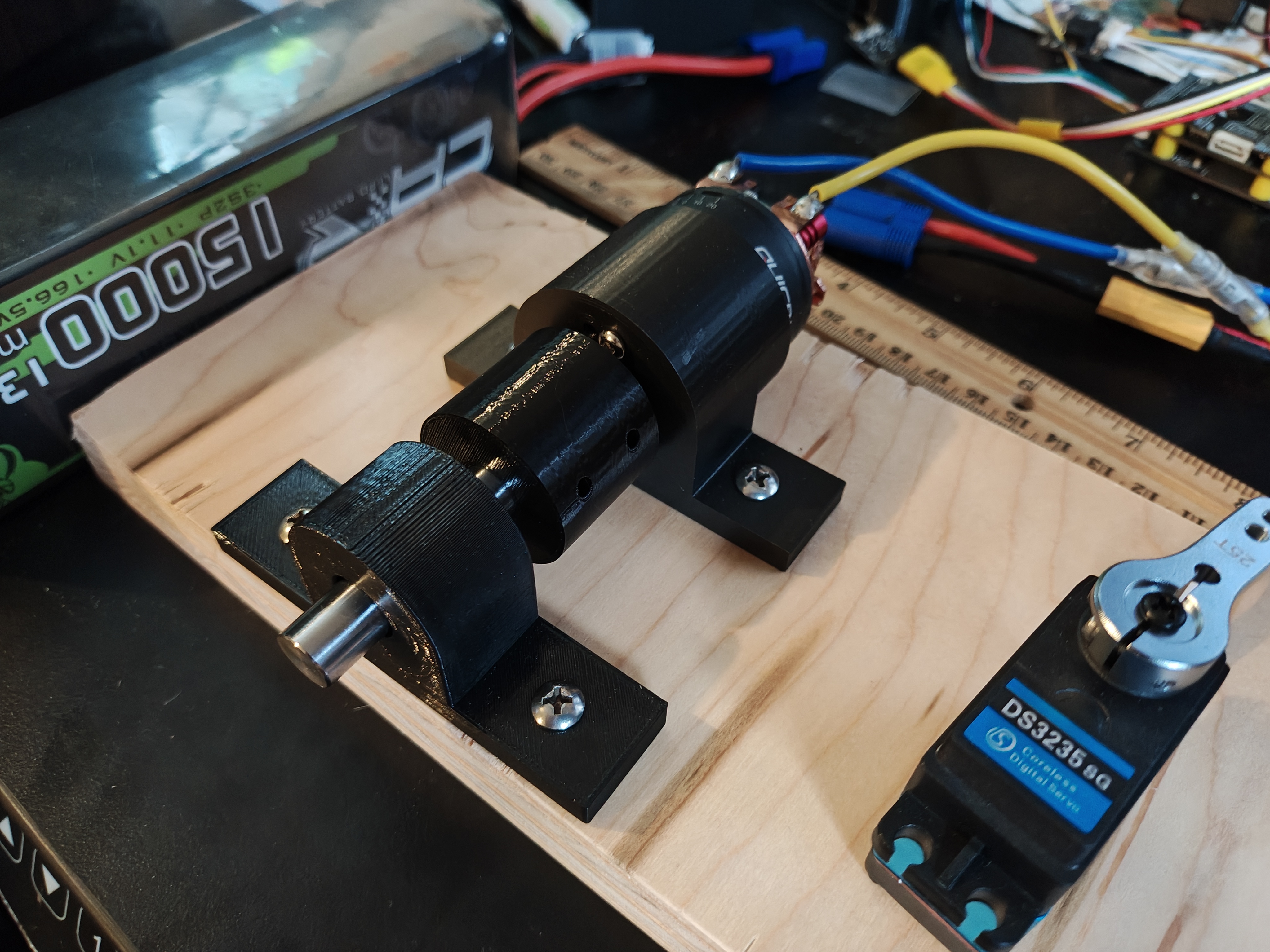 Testing the bearing housing and motor alignment
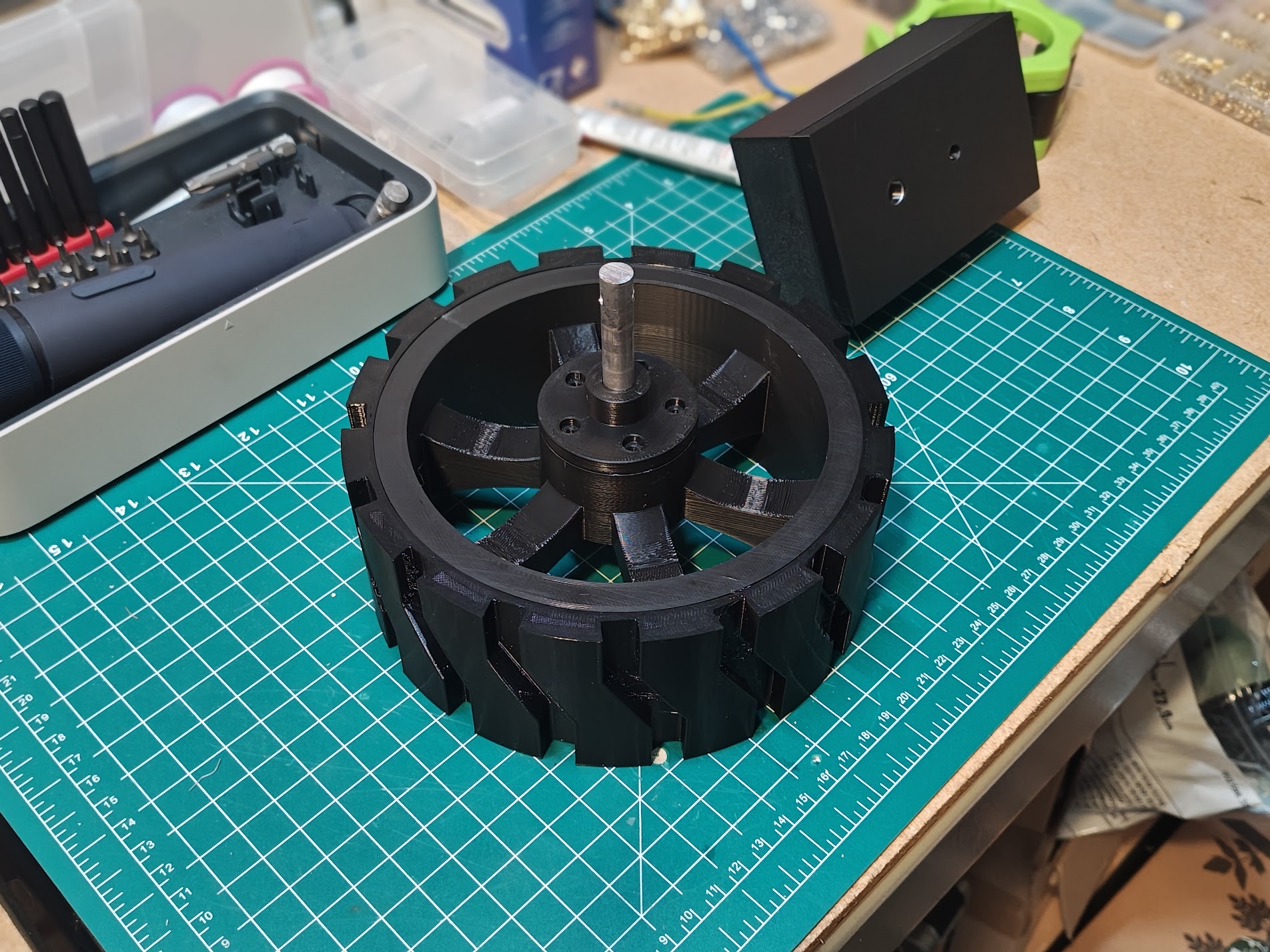
 Complete drivetrain assembly with wheel attached
The initial test drive was humbling. The rover couldn’t drive over a small power cord in the garage. When I pushed throttle to the max, one of the motors started smoking. That’s when I knew I couldn’t get away from learning about gears and gear boxes.
*Test drive before the gearbox redesign*I designed a 2-stage gearbox that gives a 40:1 reduction. There are way cooler gear assemblies out there, but this one is mine.
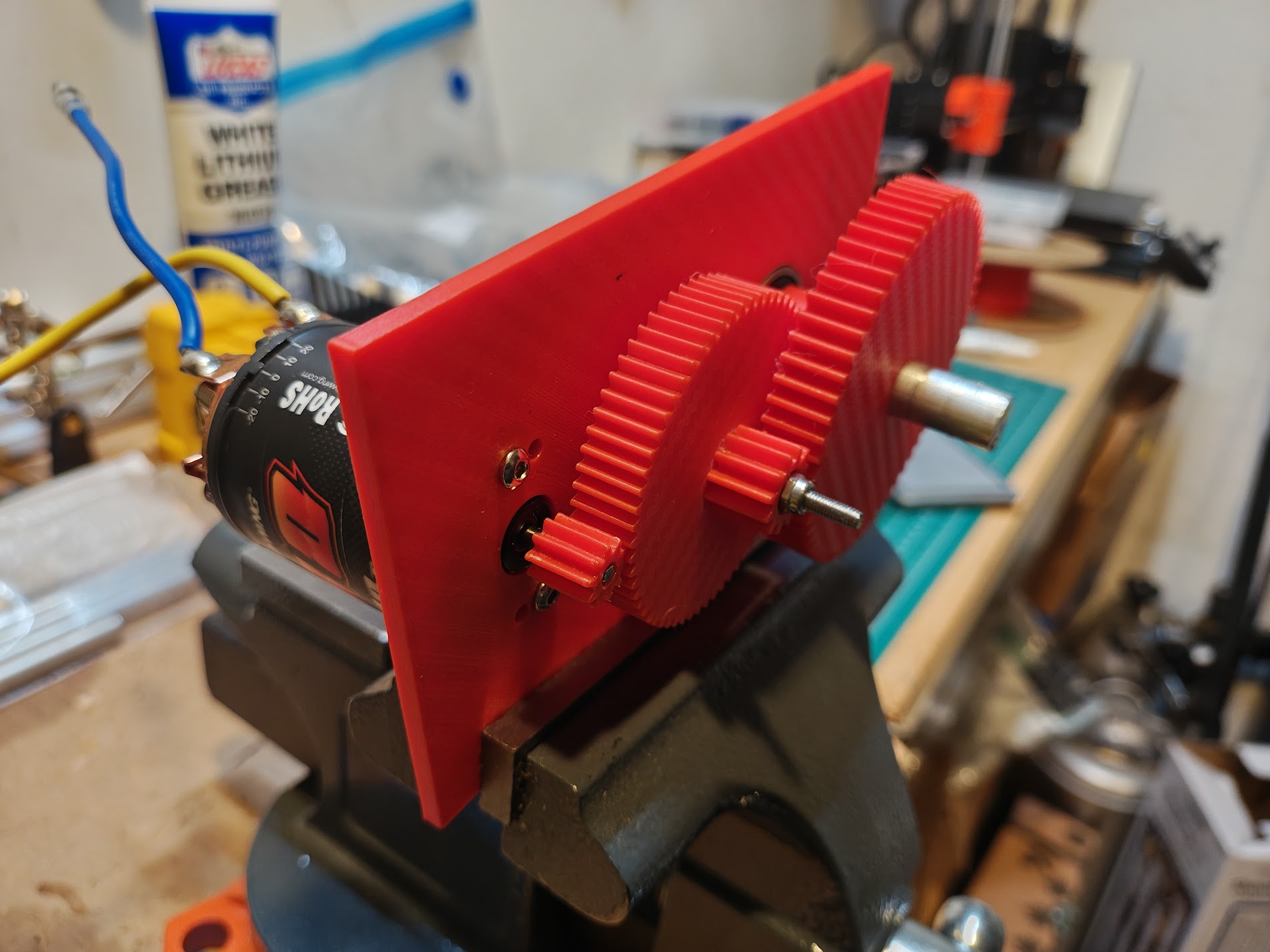 2-stage gearbox with motor attached
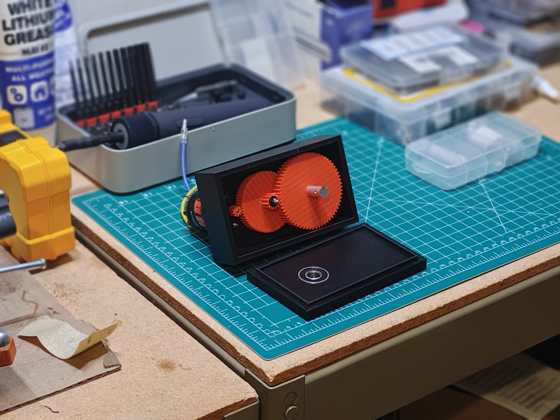 Current gearbox with red spur gears
 Gearbox and motor assembly with wheel attached
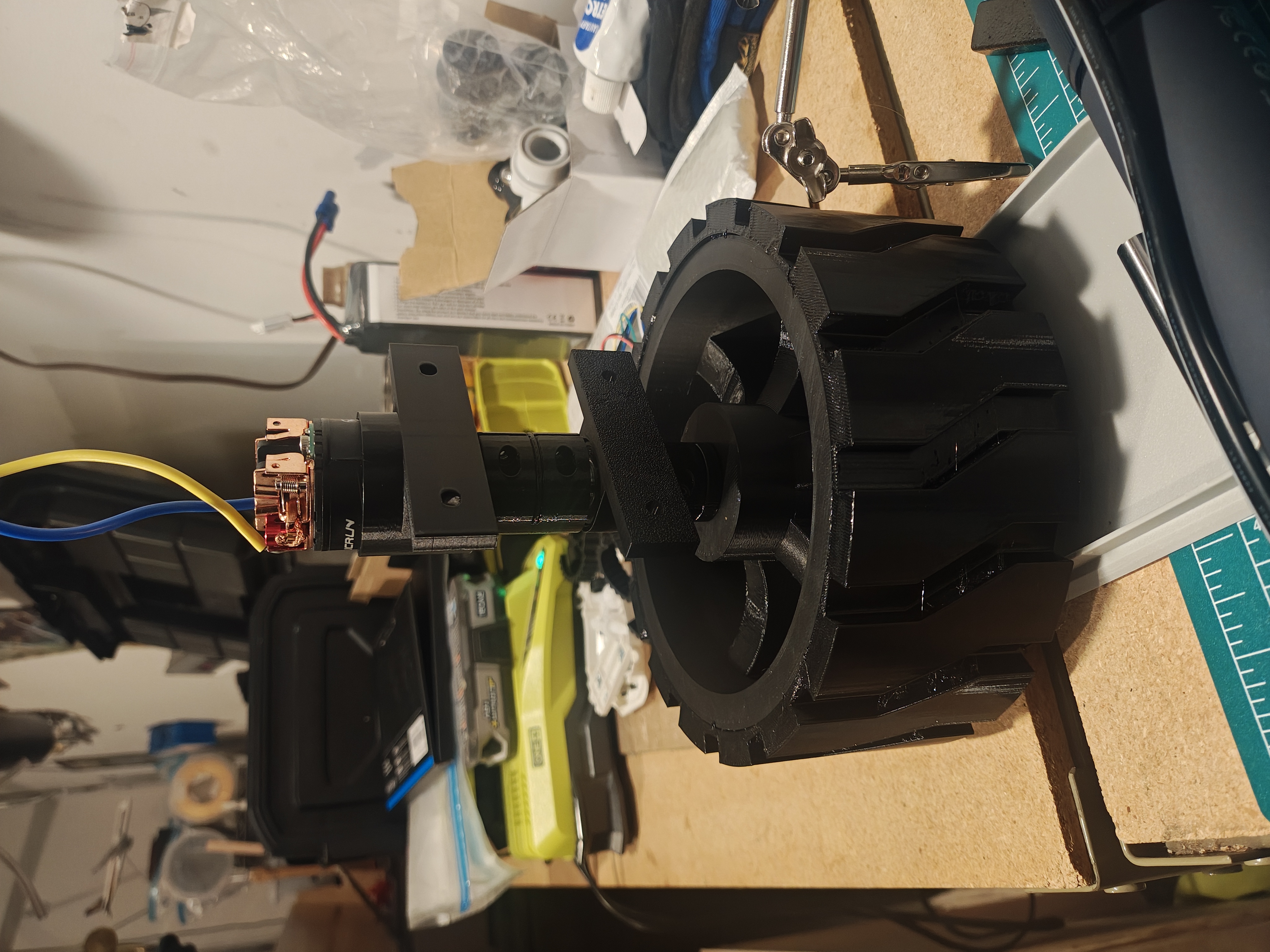
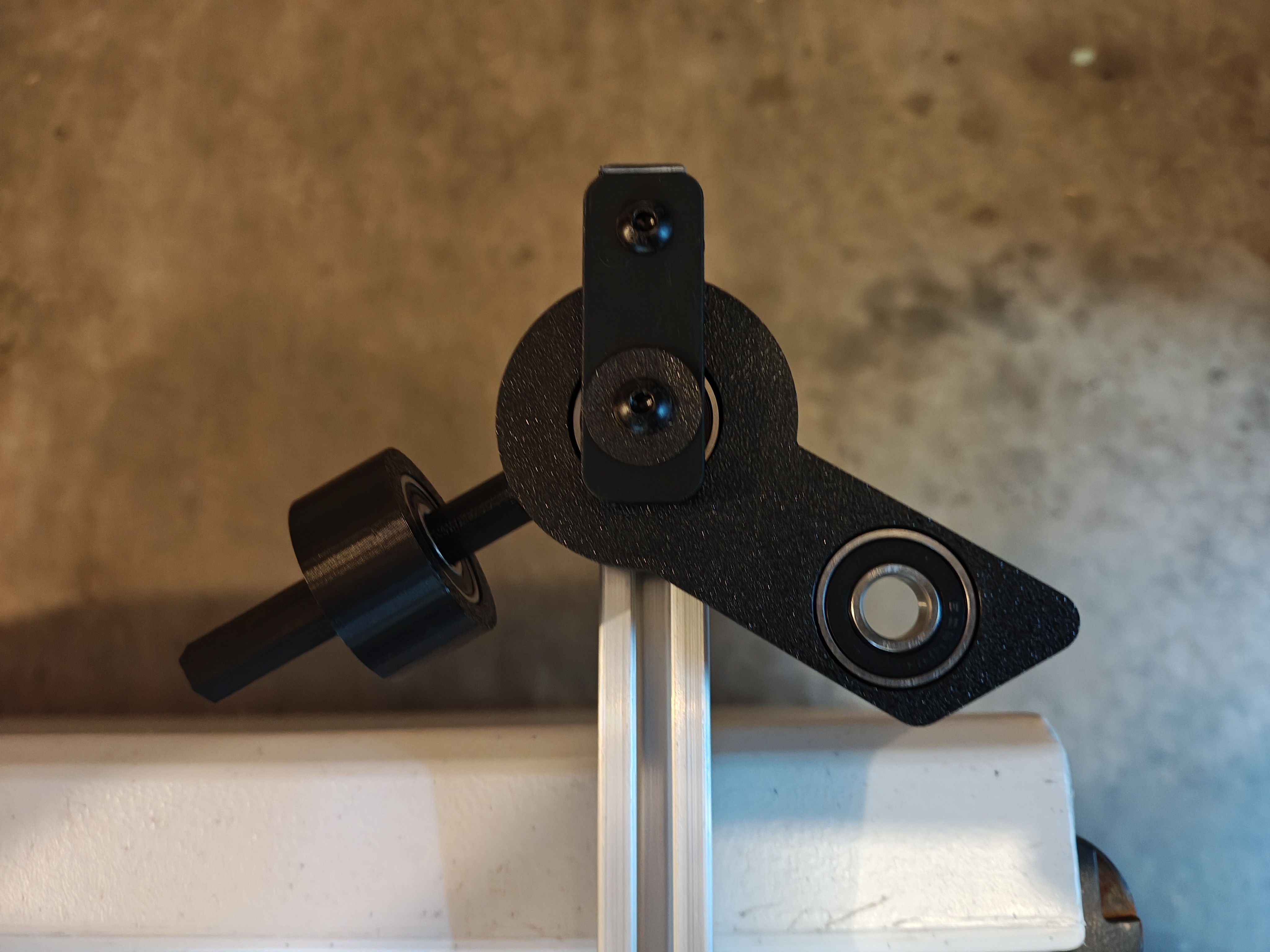
Integrating the gearbox into the rover turned out to be its own challenge. The gearbox output doesn’t line up with the wheel height — fixing that would destroy ground clearance and require a full frame redesign. Instead, I’m using a dual cardan universal joint to connect the gearbox to the wheel at an angle. A single universal joint causes the output to oscillate faster and slower through each rotation even at constant input speed. A dual cardan joint uses two universal joints so the oscillations cancel, giving constant velocity output.
I found 3D printable universal joint models for 5-10mm shafts that worked for prototyping, but I needed a model in Onshape to get the measurements right before cutting aluminum rods. So I designed my own.
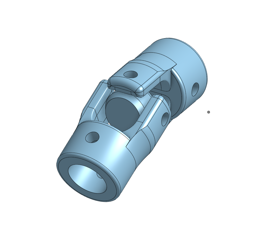 Custom universal joint design
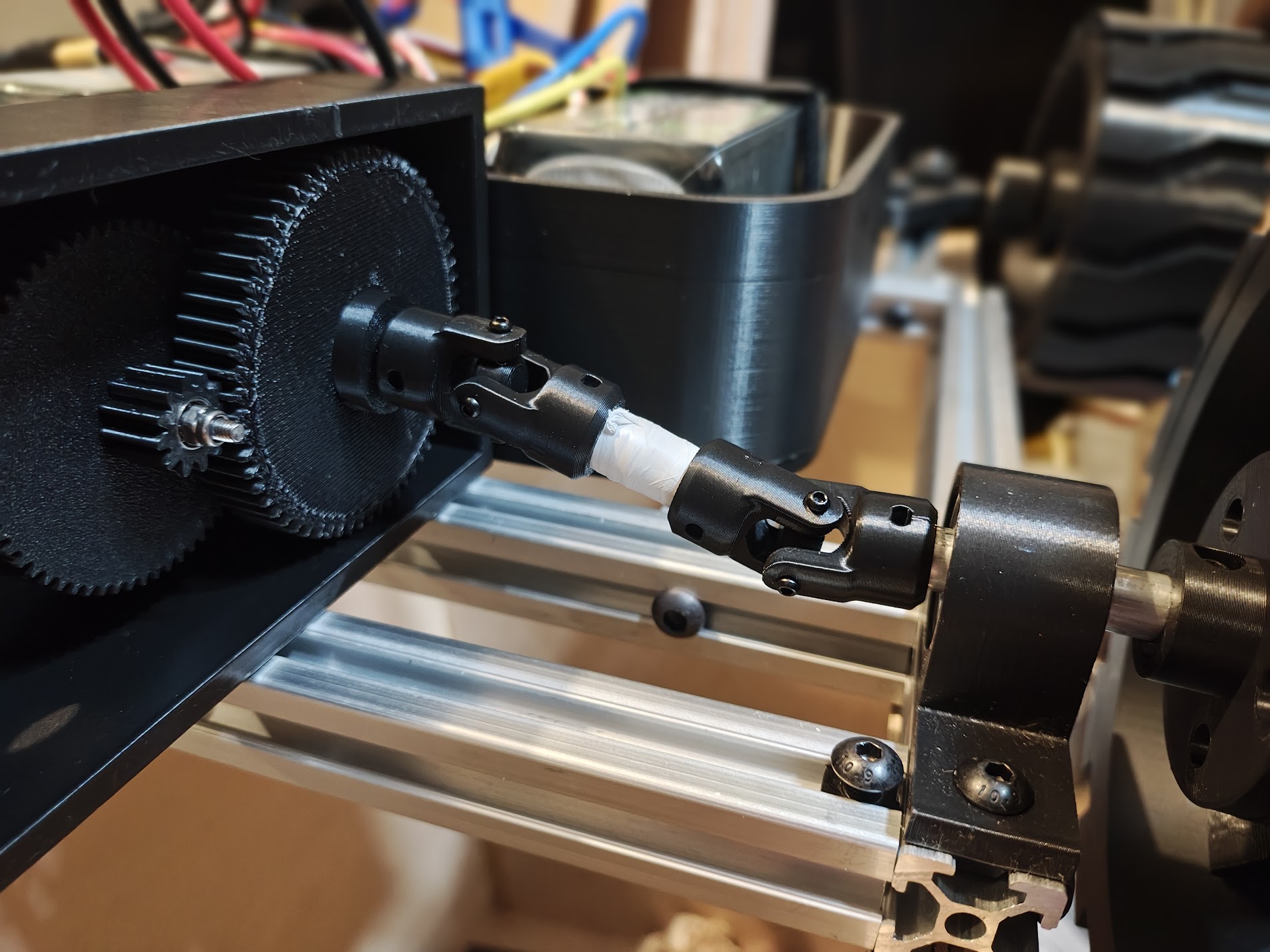 Dual cardan universal joint prototype
With the right-side linkage done, I mirrored it for the left side and hit a new problem: both gearboxes have their motors pointing toward the center of the rover, so when mirrored they collide.
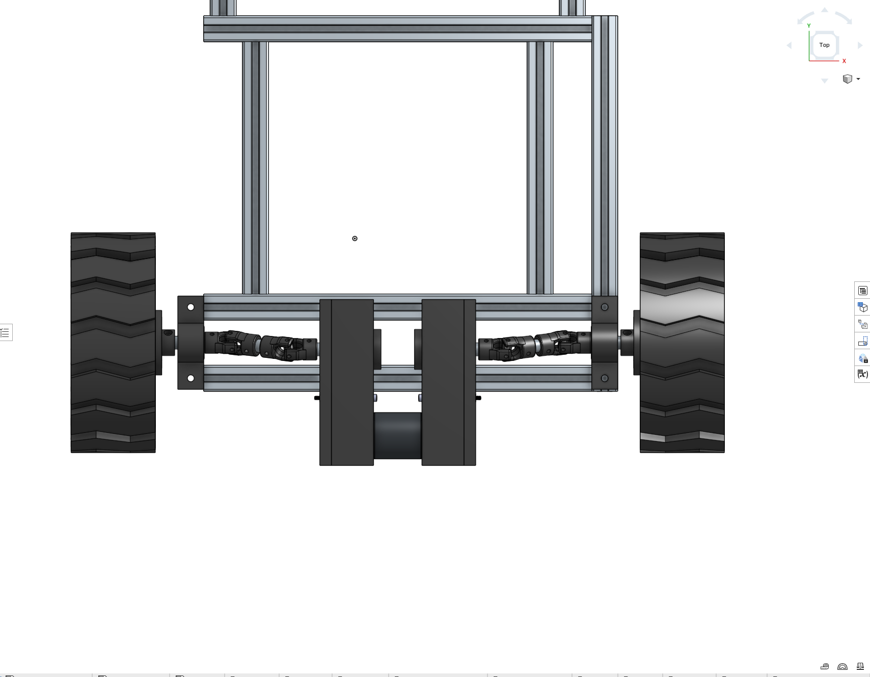 Motor overlap with both gearboxes in place
The fix was to redesign the gearbox so the output shaft exits the same side as the motor. Flipping it puts the motor toward the wheel instead of the center — no more overlap.
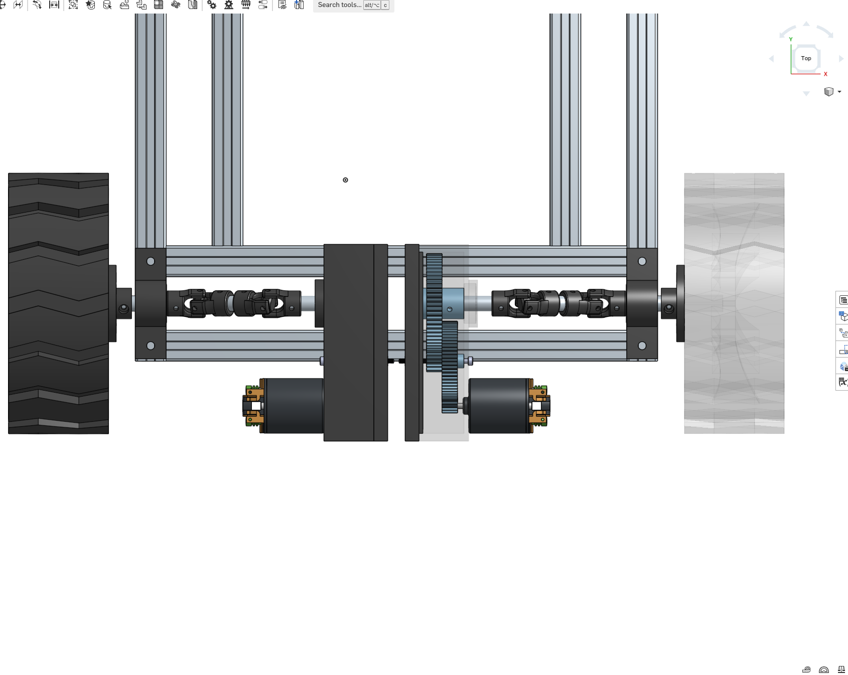 Redesigned gearboxes — motors no longer overlapping
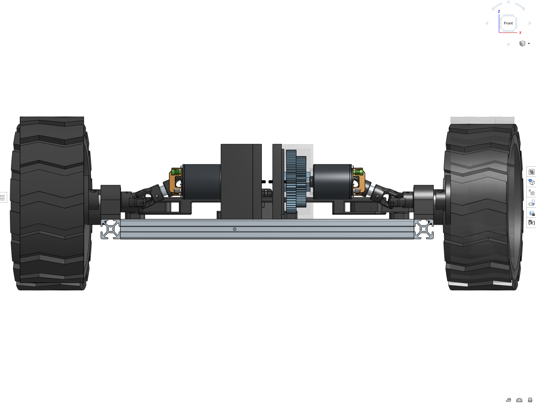 Front view of the rear axle
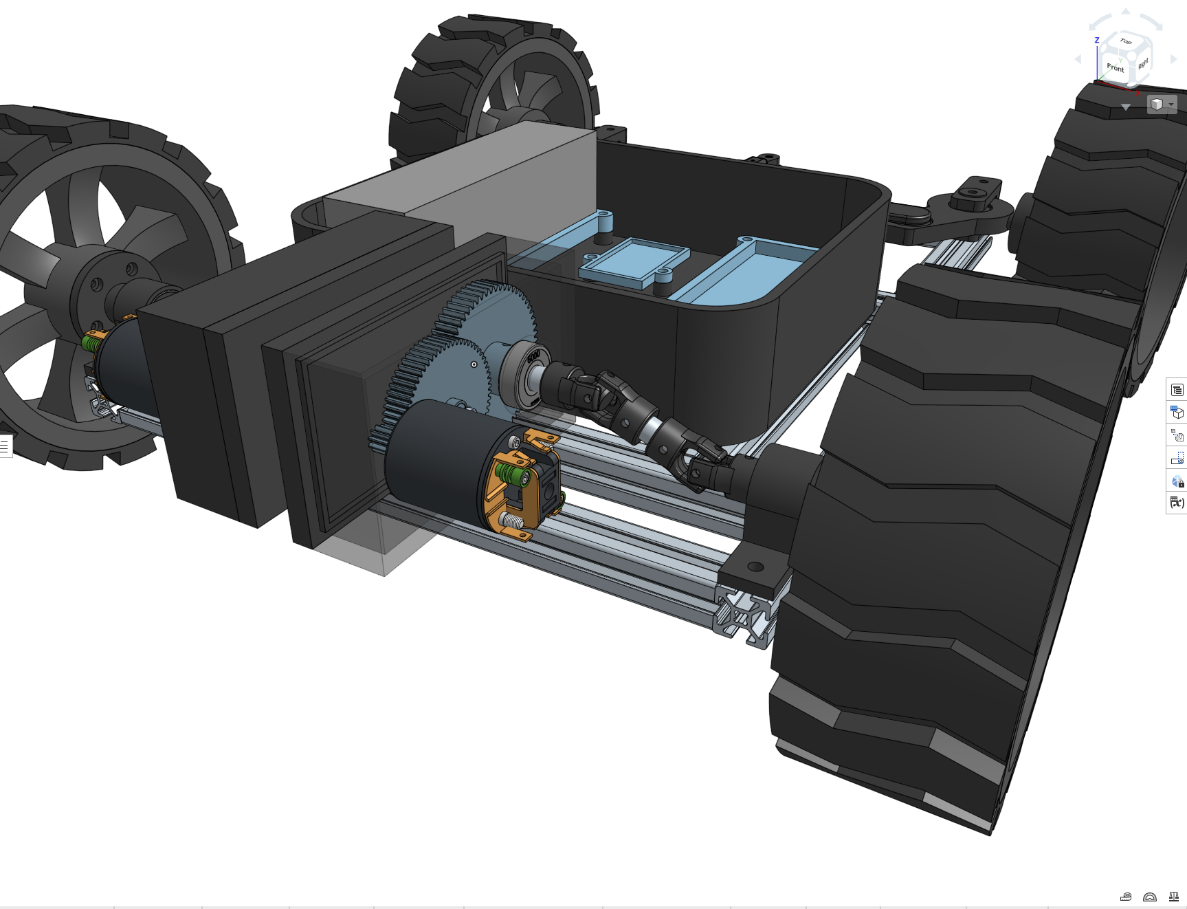 Gearbox in context with the rest of the rover
The gearbox mount ended up being straightforward. With all the pieces together, I ran the first test of a complete drivetrain assembly — motor, gearbox, CV joints, and wheel — all spinning together for the first time.
*First test of the fully assembled drivetrain for one wheel*Right now I’m printing parts and assembling, waiting to find the next problem.
Steering
 Ackerman steering geometry in motion
The steering knuckles are 3D-printed and implement Ackerman geometry. The inside wheel turns sharper than the outside wheel through a turn, just like a car. Skid-steer would’ve been simpler mechanically, but it tears up the tires and fights ArduPilot’s GroundSteering logic. A Zoskay DS3235 servo provides 35kg-cm of torque, enough to turn the wheels even when the rover is sitting still on pavement.
The servo mount took four tries to get right. First one didn’t fit the servo. Second one had screw holes that were too big. Third one didn’t account for the wire coming out of the servo. Fourth time I just removed one side of the mount entirely so the servo could slide in from the side. Sometimes the simple solution is the one you should’ve tried first.
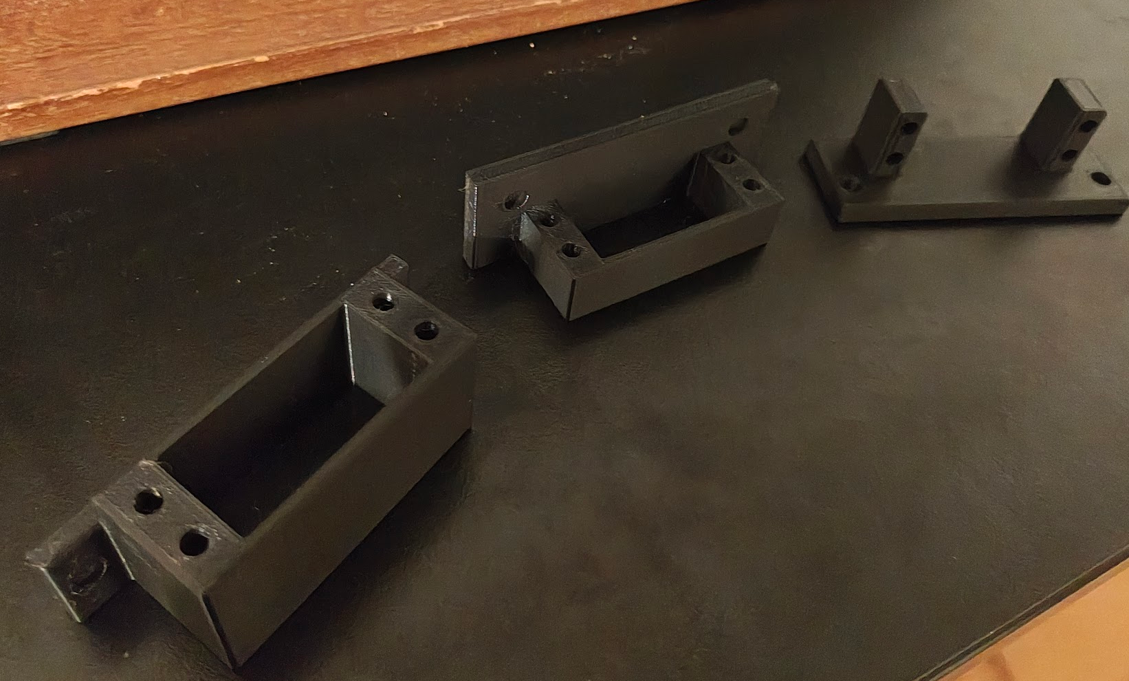 Four iterations of servo mounts before getting it right
 Steering knuckle mounted to the frame
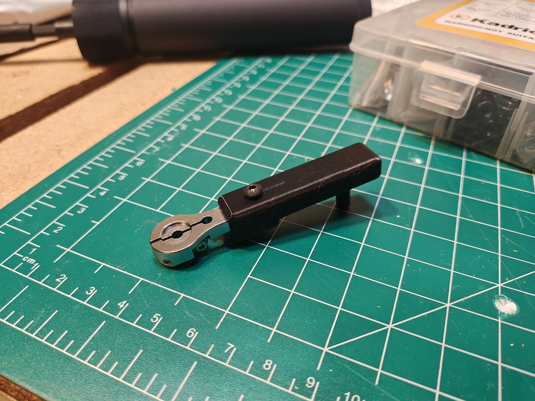 Custom servo arm sleeve for the steering linkage
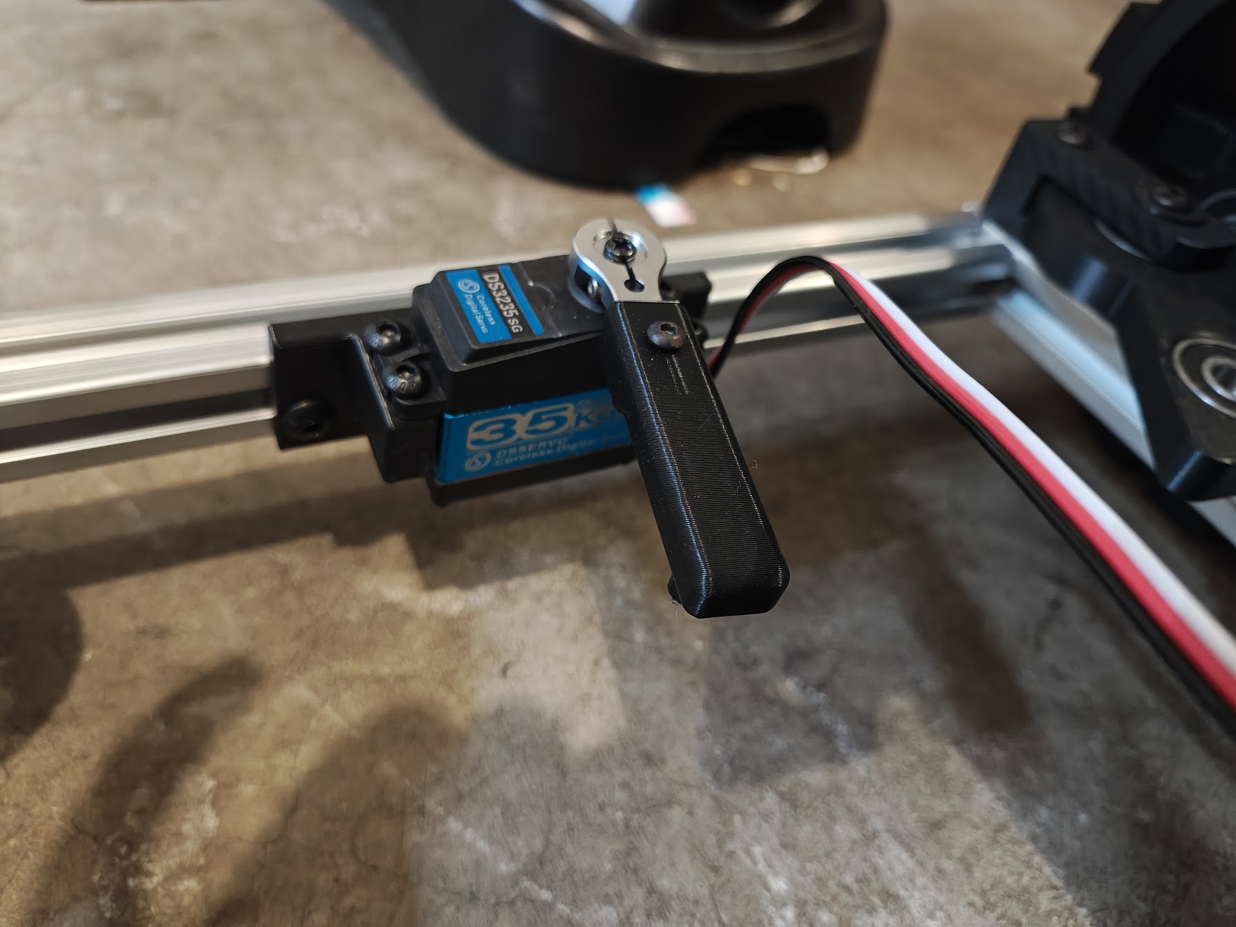 Servo installed with mount and custom arm
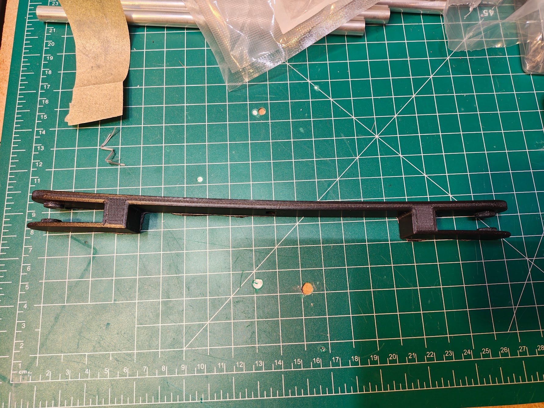 Steering linkage
 Steering assembly mounted on the frame
Wheels and Tires
I printed my own wheels. Standard curbs are about 15cm, so I went with 17cm diameter to clear them with some margin. They’re 6.5cm wide, with a hex hub interface so they pop on and off easily. The wheels are PLA, rigid enough to hold their shape. The tires are TPU, flexible and grippy. I went with 6000RS bearings over cheaper 608 skateboard bearings because the deeper groove handles radial loads better when you’re hauling beer over rough terrain. Press-fitting them into PLA hubs requires getting the hole diameter exactly right. Too tight and the bearing won’t go in. Too loose and it falls out. I got it right eventually.
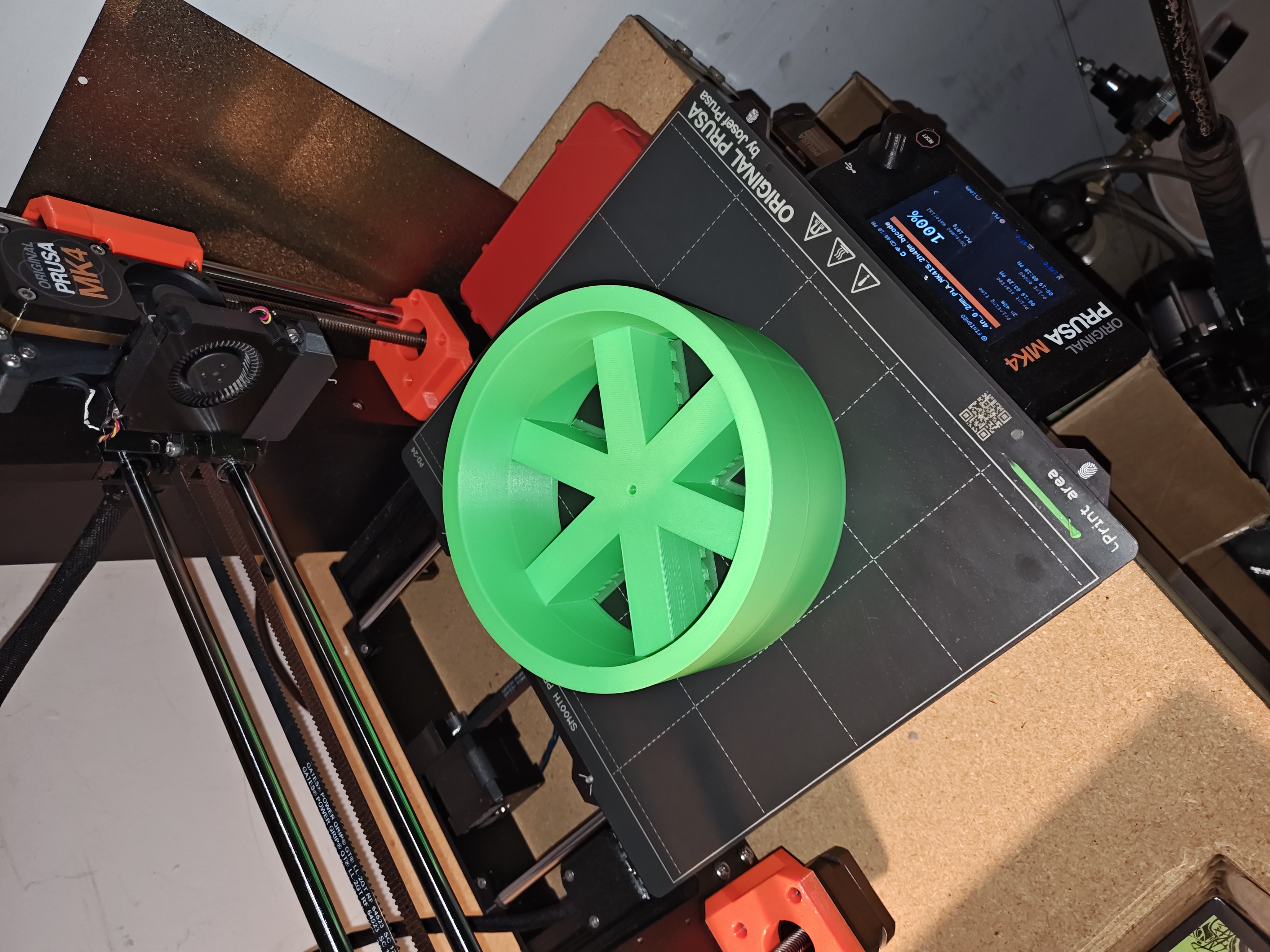 PLA wheel hub fresh off the printer
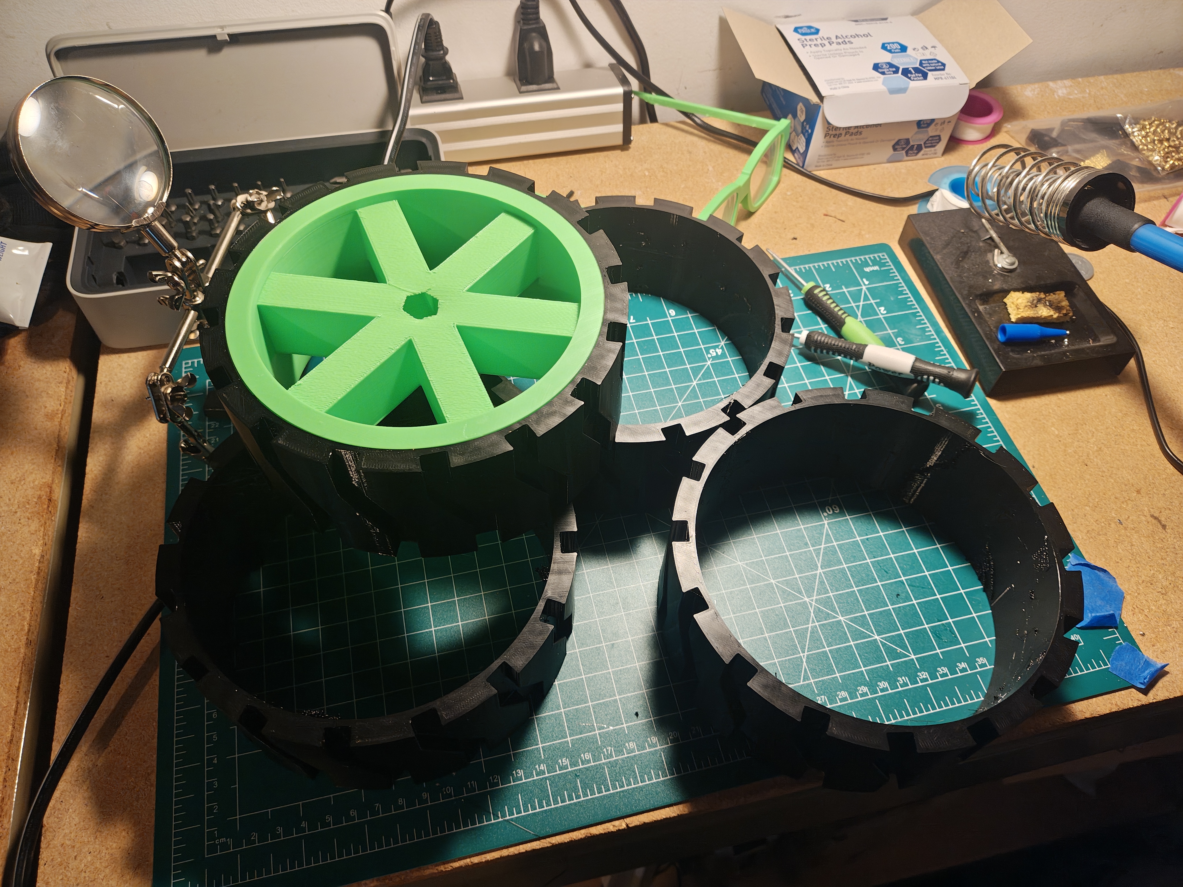 Tire fit on wheel prototype
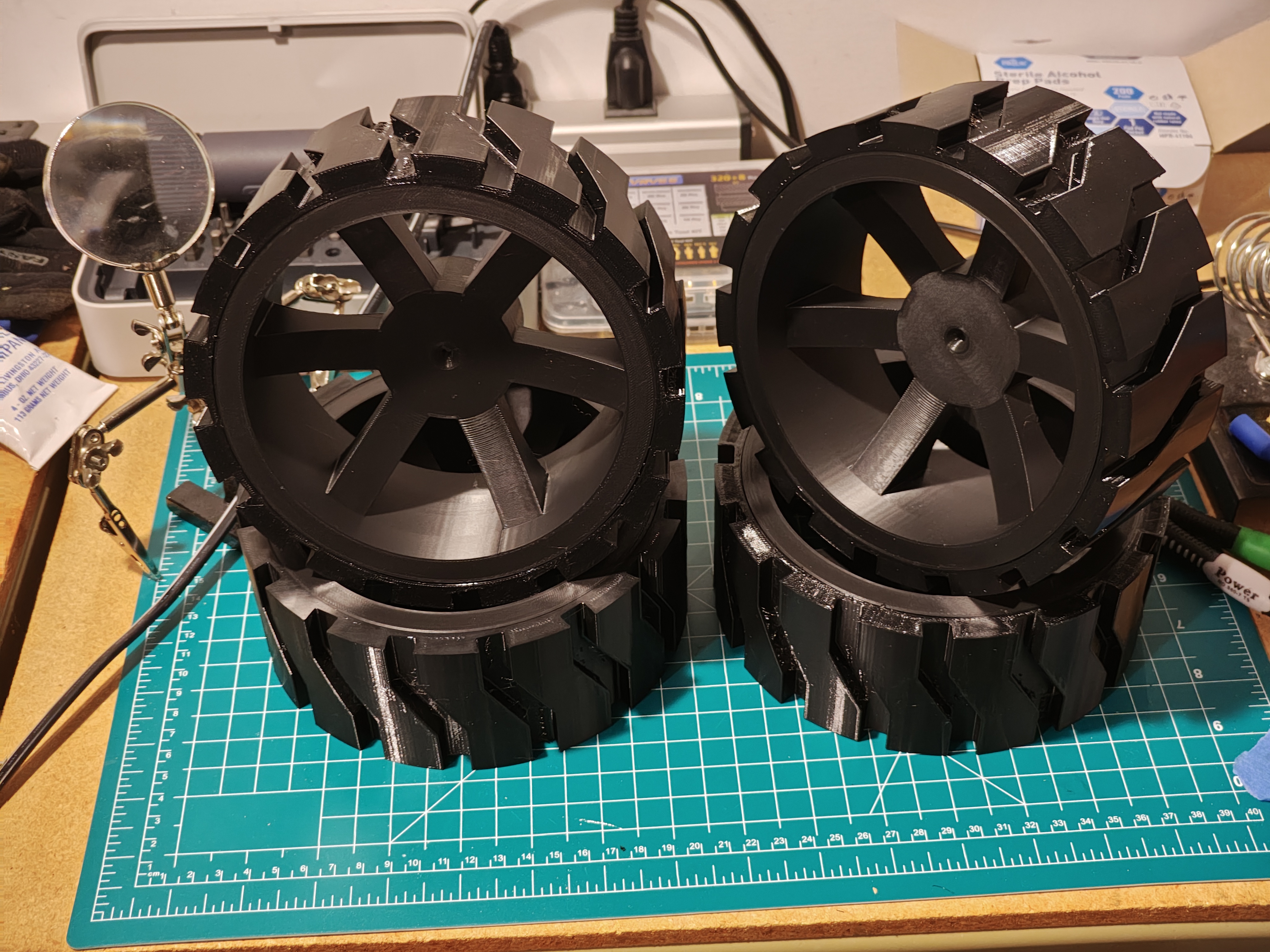 Final wheels and tires
The gearbox redesign needed a new drive wheel hub. I went with a 5-lug design, planning to use heat inserts in the wheel so the hub could bolt on cleanly. The problem was the lack of infill in the wheel. The heat inserts just fell right into the plastic. I don’t want to waste the wheels though, so super glue will work for now. If I need to reprint the wheels I’ll bump up the infill, though I didn’t keep track of what I used for these ones. Lesson learned on documenting print settings. But I probably won’t keep track of the next ones either.
 New 5-lug wheel hub
 Hub mounted in the wheel
Electronics
The brain is a SpeedyBee F405 WING running ArduPilot Rover firmware. It’s a flight controller, but ArduPilot doesn’t care that I’m on the ground. GPS comes from a Matek M10Q-5883 module with a built-in compass. RC control uses ExpressLRS protocol. Low latency, good range, and if I mess up the autonomous navigation I can take over manually.
Power is two 3S LiPo batteries, 15000mAh each. That’s 333Wh total, which should be enough to deliver a lot of beer before needing a recharge. Laying everything out on the garage floor helped me figure out what size enclosure I’d need.
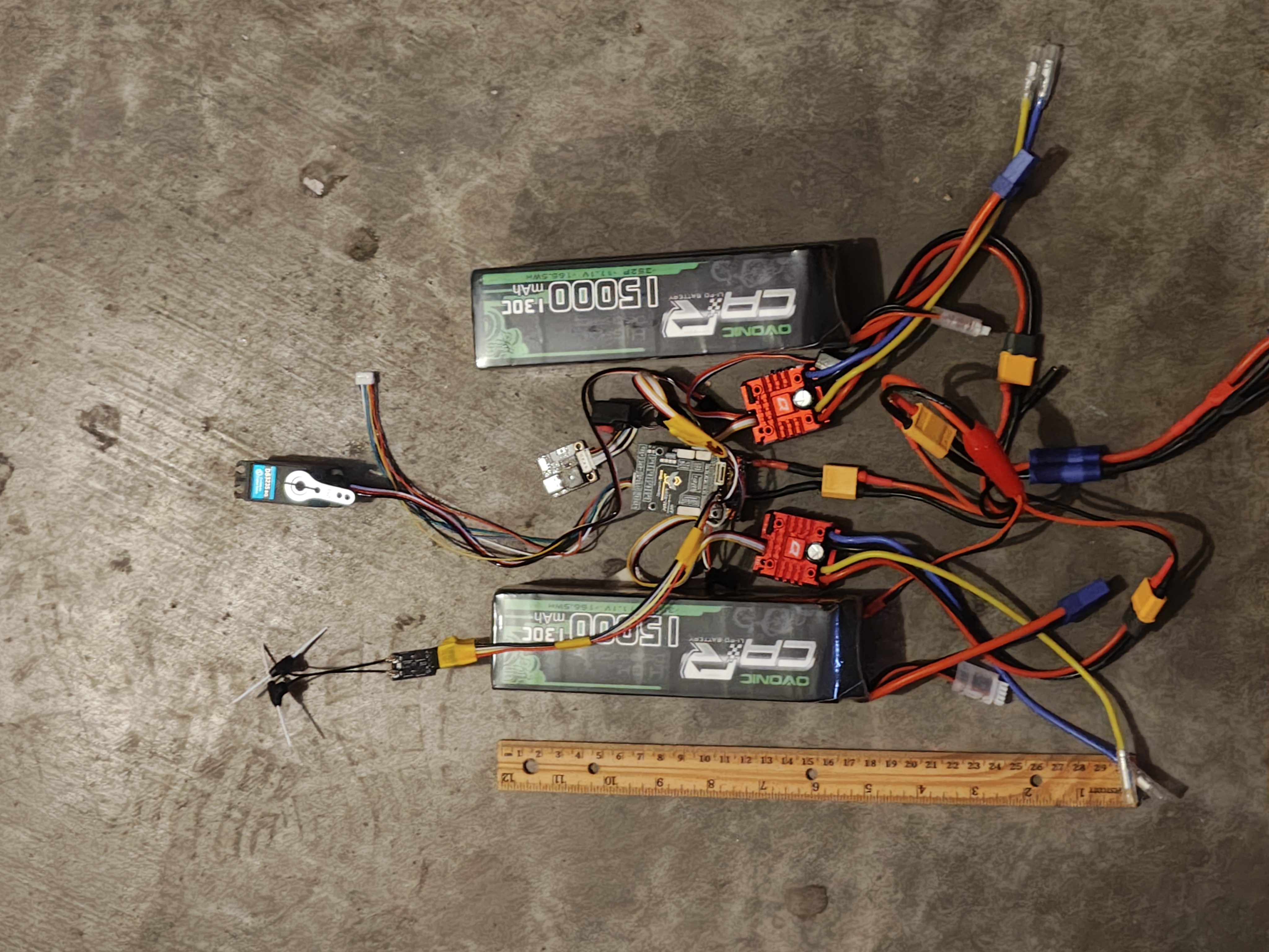 Planning the electronics layout on the garage floor
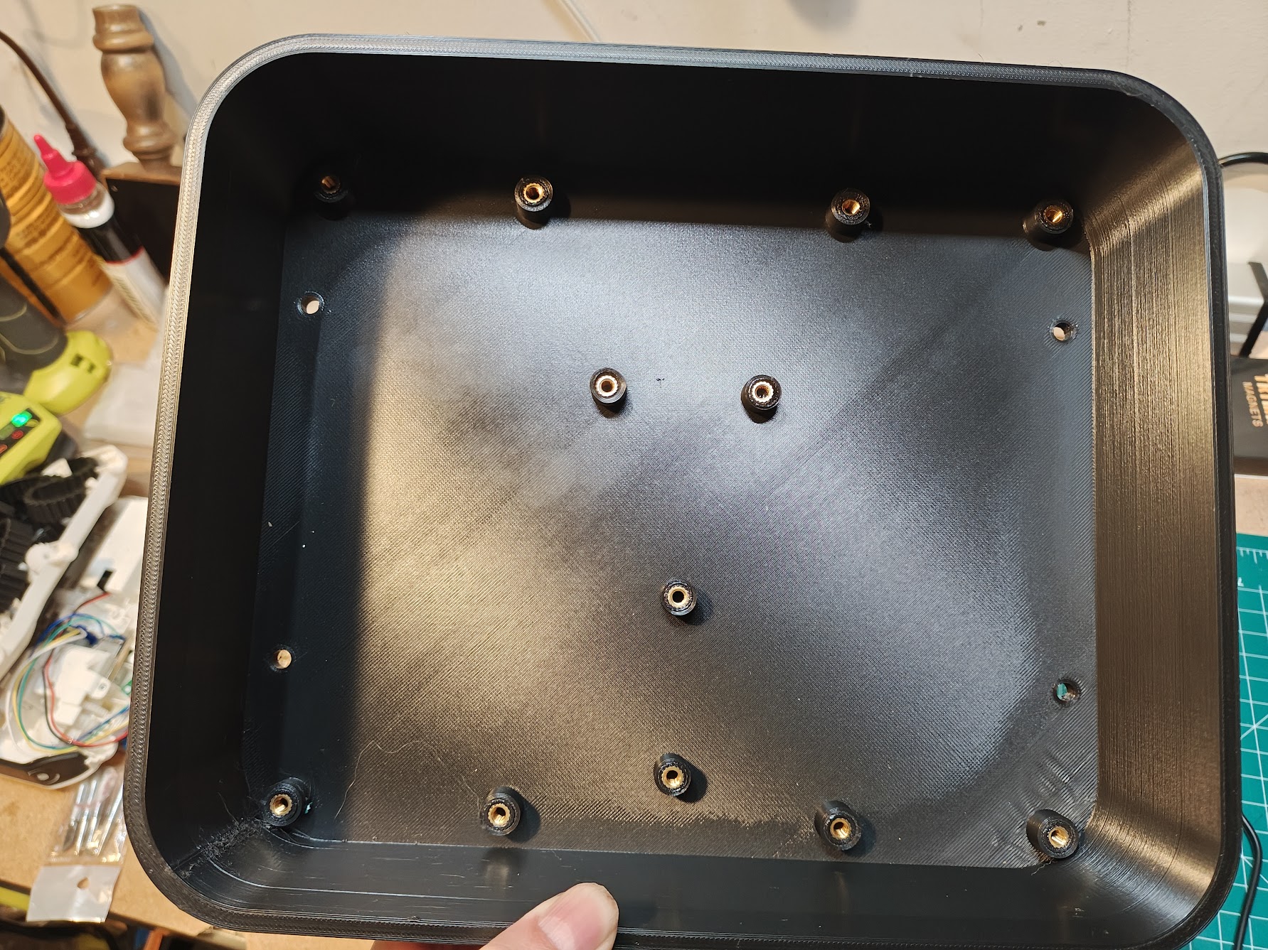 Enclosure with heat inserts installed
Inside the enclosure, I designed caddies for the batteries, flight controller, and ESCs. Each component velcro-straps to a caddy, and the caddies screw into the enclosure where I added heat inserts. It keeps everything modular and easy to swap out when I inevitably fry something.
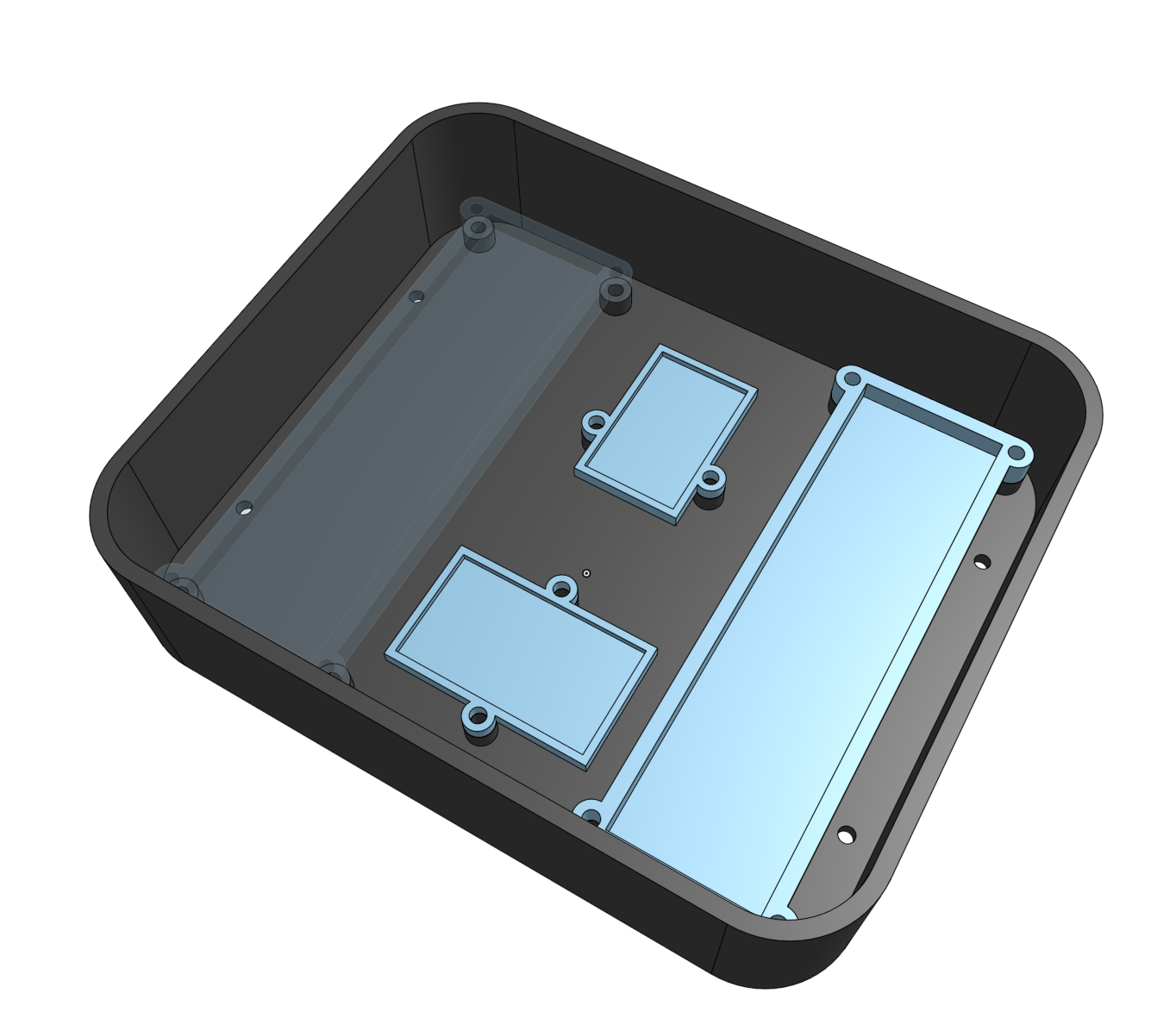 Enclosure with component caddies
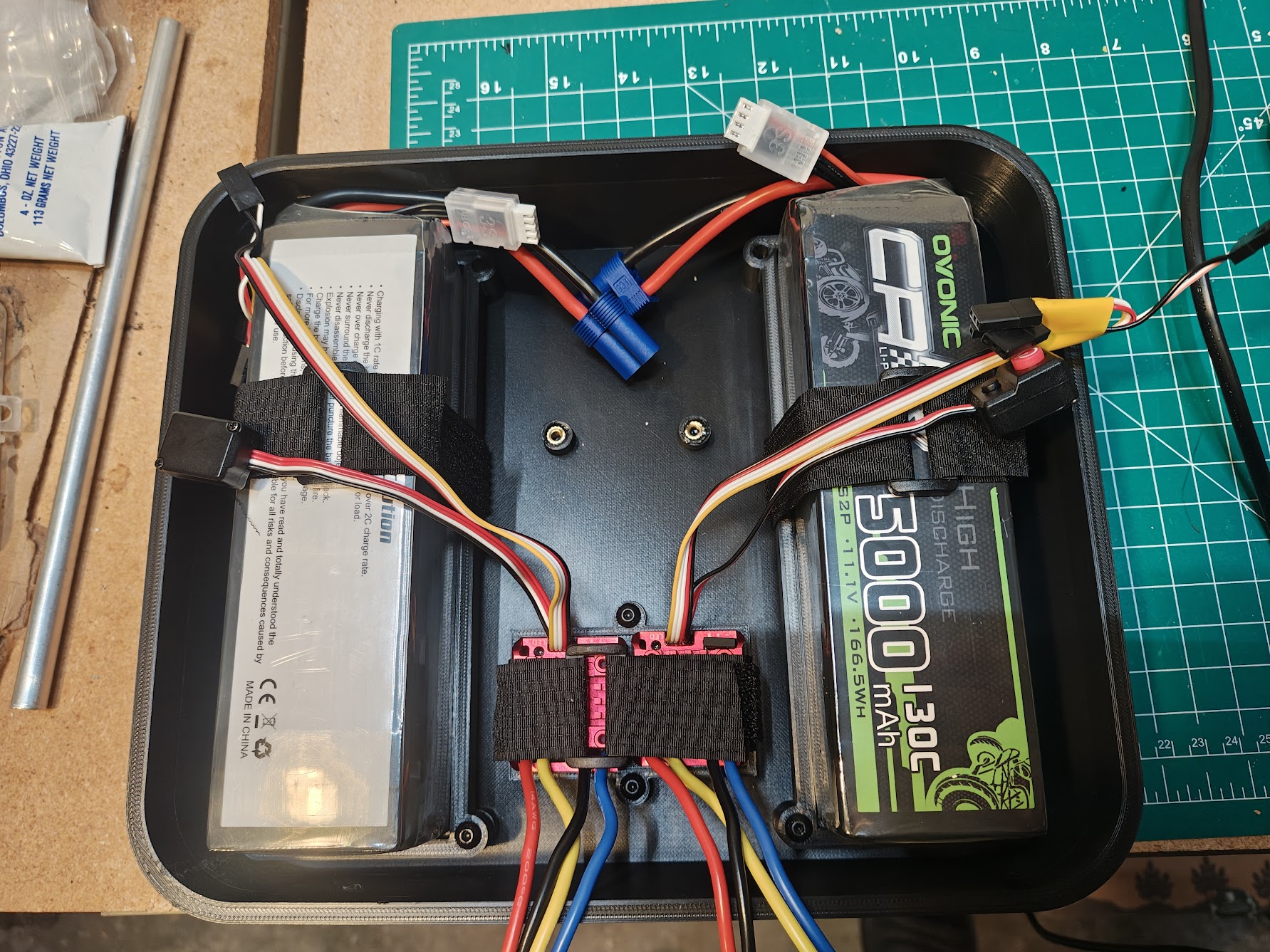 Enclosure with batteries and ESCs installed in caddies
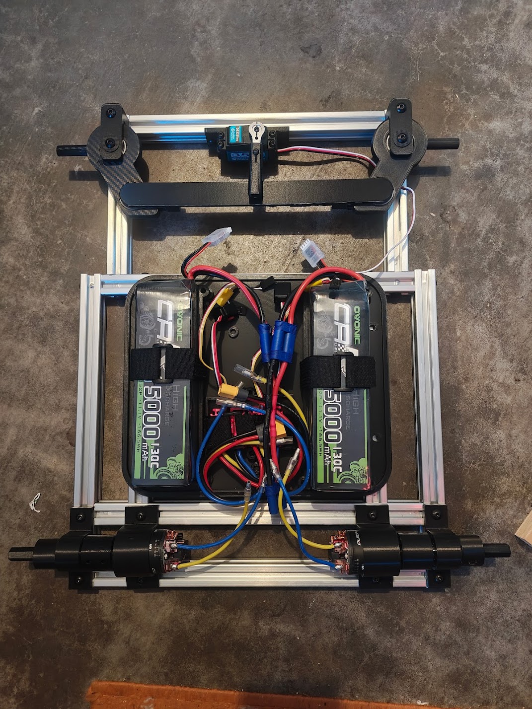 Dry fit of major components without wheels
ArduPilot Configuration
I spent three days figuring out that “Roll” controls steering in rover mode, not “Yaw” like you’d expect. The motors use SERVO function 70 (throttle), and steering uses function 26 (GroundSteering). Now it makes sense. At the time, it did not.
Specifications
| Requirement | Specification |
|---|---|
| Payload capacity | 10 lbs |
| Target speed | ~3 mph |
| Terrain | Paved surfaces, sidewalks, curbs, grass, mild grades |
| Navigation | GPS waypoint autonomy via ArduPilot |
| Operating range | Multi-kilometer |
| System | Component | Details |
|---|---|---|
| Frame | 2020 aluminum extrusion | 24” x 18” bolted frame |
| Drivetrain | Brushed DC motors | Dual HOBBYWING QUICRUN 1080 G2 ESCs, 540 40T motors |
| Steering | Ackerman geometry | Zoskay DS3235 servo (35kg-cm torque) |
| Flight controller | SpeedyBee F405 WING | STM32F405 @ 168MHz, ArduPilot Rover firmware |
| GPS | Matek M10Q-5883 | GPS + magnetometer module |
| Power | Dual 3S LiPo | 15000mAh each, 333Wh total capacity |
| Wheels | Custom 3D-printed | 17cm diameter, 6.5cm width, 6000RS bearings |
| RC | ExpressLRS | Radiomaster TX12 MKII transmitter, BetaFPV SuperD receiver |
See Also
- CAD Models - Onshape renders and design views
- Design Notes and Calculations - Hand-drawn sketches and calculations